
What Is a Threaded Linear Shaft and How Does It Work?

A Threaded Linear Shaft turns rotary motion into controlled straight-line travel. Its helical thread engages a nut, so each shaft rotation moves the nut along the shaft. The travel distance depends on thread lead, while friction, load, and support affect performance. In a small actuator, the motion may push a carriage across a guide; in a workshop fixture, it may adjust a clamp by hand. Simple in principle. Sensitive in practice.

Precision machine design expert Alexander H. Slocum is often associated with the reminder, “The design of a machine is the design of its errors.” That idea matters here: shaft alignment, thread accuracy, lubrication, and mounting can all influence smoothness and repeatability. A Threaded Linear Shaft is not automatically a precision assembly. The nut may bind if the shaft is misaligned, and backlash can affect positioning when motion reverses. These details deserve attention.

This introduction explores how the mechanism works, what its main components do, and where different thread forms fit. It also considers load capacity, speed, wear, and practical selection. One limitation is easy to overlook: a threaded shaft can look sturdy yet perform poorly when its supports or nut are mismatched. The right choice depends on the motion required, the working environment, and acceptable maintenance—not appearance alone.
What Is a Threaded Linear Shaft and How Does It Work?

What Is a Threaded Linear Shaft?

A threaded linear shaft is a cylindrical machine element with helical threads along its length. A matching nut engages those threads, converting rotation into controlled movement along an axis. The shaft may turn while the nut travels, or the nut may rotate around a fixed shaft. Travel per revolution depends on thread lead, which can differ from the spacing between adjacent threads. That distinction is easy to miss. Unlike a smooth guide shaft, a threaded shaft helps generate motion and can carry axial loads. A separate linear guide may still be needed to resist side forces and prevent carriage rotation.

Engineers typically assess load, travel speed, duty cycle, thread form, straightness, and end machining. Material and lubrication matter, too; dust or moisture can change wear behavior. Pitch can be deceptive. Multi-start threads, for example, advance farther per revolution than single-start threads with the same pitch. A 2023 MarketsandMarkets report estimated the global motion-control market at $16.4 billion and projected $22.9 billion by 2028. Those figures cover a broad equipment market, not threaded shafts alone, but they show the scale of industrial motion applications. In practice, a shaft’s nominal diameter is not enough to select a working assembly. Nut compatibility, backlash, support, and alignment need checking. Real installations are rarely as tidy as a drawing.

What Are Its Main Components and Thread Types?

A threaded linear shaft combines a straight guide surface with one or more threaded sections. The smooth section supports linear bearings or bushings, while the threads attach end supports, collars, or other parts. Some designs use a threaded section with a matching nut to create controlled travel. These functions are related, but not interchangeable. A bearing needs a smooth, accurately sized running surface; a drive nut needs threads that match its profile and pitch.

Thread type depends on the job. Metric and Unified threads commonly secure components, with size and pitch selected to match the mating part. Trapezoidal or Acme threads are better suited to transmitting motion, because their profiles handle axial loads more effectively than ordinary fastening threads. Square threads can also transmit motion efficiently, though they are less common and harder to manufacture. Check thread direction, pitch, diameter, and fit before assembly. A nut that starts unevenly may damage the shaft. That detail is easy to miss. In practice, inspect the shaft’s finish and alignment too; a thread can be correct while the bearing surface still causes binding.

What Is a Threaded Linear Shaft and How Does It Work?

Linear Travel per Turn for Single-Start ISO Metric Coarse Threads

A threaded linear shaft converts rotation into linear motion: for a single-start thread, one full turn moves the nut forward by one thread pitch. The chart shows standard coarse-pitch examples; actual shaft designs may use different dimensions.

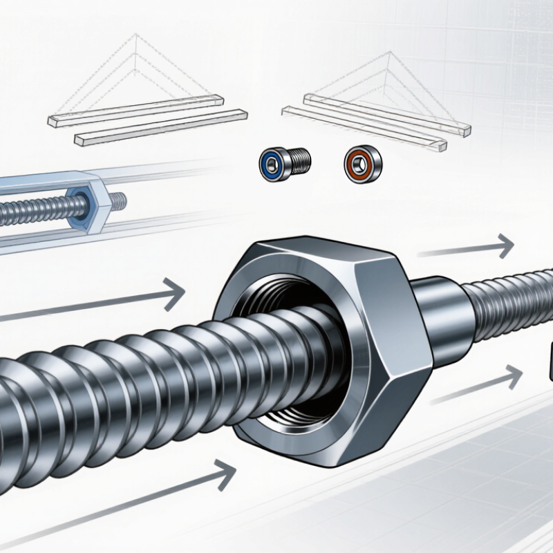
Main components: the shaft carries the threaded section, a matching nut engages the threads, and bearings and a coupling support the shaft and connect it to a drive. Common thread forms for linear motion include trapezoidal (Acme), square, and ball-screw designs; V-threads are commonly used for fastening.

How Does a Threaded Linear Shaft Convert Rotation into Motion?

A threaded linear shaft converts rotation into straight-line movement through the contact between its helical threads and a matching nut. When the shaft turns, the nut follows the thread path and moves along the shaft. In some assemblies, the shaft stays still while the nut rotates; the principle is the same. The thread’s lead determines travel: a lead of 4 millimeters moves the nut about 4 millimeters per shaft revolution. Small turns create precise adjustments. That’s the basic action.

For smooth motion, the shaft needs support, and the nut or connected carriage must be prevented from spinning freely. Bearings help control shaft movement, while guides keep the carriage aligned. If alignment is poor, friction and wear can rise quickly. Load, thread shape, lubrication, and speed also affect performance. A design that looks simple on paper may behave differently under real load; that is worth checking rather than assuming.

Tips: Measure the required travel per revolution before choosing a thread lead. Check for backlash by reversing the shaft and observing any delay before the carriage moves. Keep the shaft clean, lubricate it as specified, and watch for uneven wear. Small checks matter.

What Factors Affect Its Accuracy and Load Capacity?

What Is a Threaded Linear Shaft and How Does It Work?

A threaded linear shaft guides movement while its threads connect to a matching nut or carriage. When the shaft or nut rotates, the thread lead converts rotation into axial travel. Accuracy depends on thread lead consistency, shaft straightness, diameter tolerance, and surface finish. Even a small alignment error can cause binding or uneven motion. Installation matters more than it may seem.

Load capacity depends on shaft diameter, material, thread engagement, and how the shaft is supported. Long, unsupported sections may bend or buckle under compression, while side loads can increase wear. Speed, lubrication, and repeated starts also affect service life. A catalog rating is only a reference; real performance changes with mounting conditions and duty cycle. It is easy to overlook those details.

Tips: Check straightness and thread fit before assembly. Support the shaft near the load, and keep the nut aligned with its travel path. If motion feels rough, stop and inspect the mounting rather than forcing it. A little uncertainty remains when loads vary, so test the actual setup under controlled operating conditions.

What Is a Threaded Linear Shaft and How Does It Work? - What Factors Affect Its Accuracy and Load Capacity?

Factor How the Shaft Works Effect on Accuracy Effect on Load Capacity Practical Check or Design Consideration
Thread lead and lead error As the shaft rotates, the thread lead determines the theoretical linear travel per revolution. Manufacturing variation in lead accumulates over travel and can cause the actual position to differ from the commanded position. Lead primarily affects travel per revolution and mechanical advantage; it does not, by itself, define the allowable load. Check the specified lead tolerance over the required travel length, not only at a single thread interval.
Thread form and fit Mating internal and external threads transmit motion and force through their contacting flanks. Clearance between the mating threads can create backlash, especially when the direction of motion reverses. Thread geometry and fit influence contact stress and how load is shared across engaged threads. Choose a compatible thread form and fit. Use a suitable preload or anti-backlash arrangement when reversal accuracy matters.
Shaft diameter and root diameter The threaded shaft acts as both a motion element and a structural member. A smaller root diameter increases elastic deflection under axial force or torque, which can shift the working position. Axial strength, torsional strength, and buckling resistance depend on the shaft’s effective cross-section; the thread root is often the critical section. Base strength calculations on the thread root diameter and verify the complete assembly, including supports and nuts.
Unsupported length and end support Bearings or other supports locate the shaft and constrain its movement while it rotates. Long or poorly supported shafts can deflect, vibrate, or run off-axis, reducing repeatable positioning. For a compression-loaded shaft, the ideal Euler buckling load is Pcr = π²EI/(KL)², where E is elastic modulus, I is the second moment of area, L is unsupported length, and K reflects end conditions. Check buckling at the longest unsupported span and use the actual support conditions. The formula is an idealized estimate, not a working-load rating.
Axial stiffness and applied force The shaft and its supports deform elastically when carrying an axial load. Elastic movement can create position error even when the thread lead is accurate. For a uniform shaft, axial stiffness is approximately k = EA/L. Greater cross-sectional area and shorter effective length generally increase axial stiffness, but allowable load must also account for strength and buckling. Estimate deflection under the actual working load and include the nut, bearings, frame, and couplings in the system stiffness assessment.
Nut engagement and load distribution The nut transfers the external load to the shaft through several engaged thread turns. Uneven contact or wear can cause changing friction and inconsistent motion. Load is not always shared equally by every engaged thread. Engagement length, material, thread quality, and alignment affect local thread stress. Use the nut and engagement length specified for the application; avoid assuming that adding engaged threads increases capacity in direct proportion.
Alignment and bearing arrangement Bearings support and guide rotation; the nut and shaft must remain properly aligned through the stroke. Misalignment can cause binding, runout, uneven backlash, and position variation. Side loads from misalignment can increase friction and wear and may overload the nut, shaft, or bearings. Check shaft straightness, bearing alignment, mounting rigidity, and whether the design permits necessary self-alignment.
Material, heat treatment, and surface finish Material properties determine how the shaft and nut respond to stress, contact, and repeated motion. Surface damage or wear can increase friction and backlash over time; heat treatment can also affect dimensional stability. Strength, hardness, fatigue behavior, and thread-root condition influence resistance to yielding, wear, and fatigue failure. Match shaft and nut materials and hardness to the load, duty cycle, environment, and lubrication method.
Lubrication and contamination Lubricant reduces friction between contacting thread surfaces; contaminants can abrade or obstruct the thread. Changing friction can affect motion smoothness and repeatability. Wear can gradually increase backlash. Inadequate lubrication or abrasive contamination can accelerate wear and reduce service life and usable capacity. Select a lubricant suitable for the materials, speed, temperature, and environment, and provide protection where debris is present.
Temperature and thermal expansion Changes in temperature cause the shaft and surrounding structure to expand or contract. Thermal growth can change the position reference and may alter clearances or preload. Temperature can affect material strength, lubricant behavior, and fit between components. For temperature-sensitive positioning, consider the full assembly’s thermal expansion and establish a consistent operating temperature.
Speed, vibration, and duty cycle Rotational speed and repeated start-stop motion determine operating conditions and dynamic forces. Vibration, runout, and speed-dependent deflection can reduce positioning repeatability. Repeated loading can cause fatigue; high speed can also increase heat and wear. A static load figure alone does not establish suitability for continuous motion. Check operating speed, acceleration, cycle frequency, lubrication, and expected service life as part of the application review.

Note: A threaded linear shaft, often used with a matching nut to convert rotary motion into linear motion, does not have one universal accuracy or load rating. Confirm the limits for the specific shaft, nut, supports, mounting arrangement, and operating conditions.

Where Are Threaded Linear Shafts Commonly Used?

Threaded linear shafts are commonly used wherever rotary motion must create controlled straight-line movement. In packaging machines, they adjust guides, sealing heads, and label sensors to match different product sizes. A motor turns the shaft, while a threaded nut travels along it. Small, precise moves.

They also appear in laboratory instruments, inspection stages, and light-duty automation equipment. An inspection stage may use a shaft to move a camera a few millimeters at a time over a component.

In workshops, threaded shafts can position clamps or adjustable stops. These applications value straightforward adjustment and repeatable travel more than high speed.

A threaded shaft is not automatically a complete linear guide. Side loads may require separate rails or bearings, and dust can collect in the thread grooves. I have seen designs look suitable on paper but bind when alignment is slightly off. That detail is easy to underestimate. Engineers should check travel distance, load, speed, lubrication, and cleanliness before selecting a shaft. In wet or abrasive environments, protection and maintenance may matter as much as the thread itself.