
What Are the Different Types of Welding Parts?
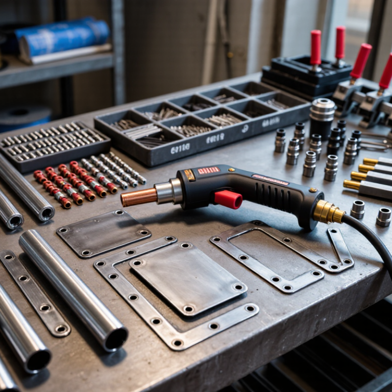
Welding Parts cover far more than the metal pieces joined by a weld. They include structural components, filler metals, electrodes, torch consumables, clamps, and replacement items such as contact tips and liners. Each plays a different role. A filler rod becomes part of the joint, while a nozzle guides shielding gas around the weld pool. Small parts matter, too.
Welding metallurgy expert John C. Lippold’s work offers a practical reminder: material, joint design, and welding process must be considered together. That principle helps explain why two parts that look similar may need different preparation or consumables. Fit matters. So does access.
This guide introduces common types of Welding Parts and explains what they do, where they are used, and what buyers should check before choosing them. We’ll distinguish base-metal components from consumables and equipment parts, then consider material compatibility, dimensions, and wear. A wrong-size liner can disrupt wire feeding; a poorly matched filler metal can compromise joint performance. These details are easy to overlook. A tidy parts chart also cannot capture every shop-floor compromise, so specifications and manufacturer guidance still matter. The aim is a clear starting point, not a substitute for qualified engineering judgment. By understanding each part’s function, readers can ask better questions and make more informed selections for their application.
Core Materials That Make Up a Weld
A weld begins with the base materials: the metal pieces being joined. Common examples include carbon steel, stainless steel, and aluminum. Their thickness, surface condition, and composition affect how heat moves through the joint. A rusty edge or oily fingerprint can interfere with fusion, so clean, dry surfaces matter. Small details count.
Filler metal may be added to fill a gap and reinforce the joint. Its composition should suit the base metal and the service conditions. In some processes, an electrode supplies this filler; in others, the electrode does not melt. Not every weld needs added filler. There is a catch: a strong-looking bead can still hide poor fusion beneath its rippled surface.
Shielding gas or flux helps protect hot metal from air, which can cause contamination or porosity. The right protection depends on the welding process and material. For example, gas coverage can be disrupted by a draft, even when the settings seem correct. Check the joint edges, filler choice, and shielding conditions together. I would not judge a weld by appearance alone. Subtle flaws can be easy to miss.
Base Metal: The Workpieces Being Joined
Base metal is the workpiece being joined, not the filler wire or electrode. Its composition, thickness, and condition shape the welding procedure. A clean steel plate behaves differently from an oily, oxidized aluminum sheet. Even small changes in alloy or thickness can affect heat flow, penetration, and cracking risk.
The scale of steel use helps explain why it is a frequent fabrication material. The World Steel Association’s World Steel in Figures 2024 reports global crude steel production of 1,892.2 million tonnes in 2023. The International Aluminium Institute reports roughly 70.6 million tonnes of primary aluminum production that year. These figures describe production, not welding demand, but they show the broad industrial presence of both metals. Steel often tolerates a wider range of shop conditions; aluminum conducts heat rapidly and needs careful cleaning before welding. That distinction matters.
Before welding, identify the base metal grade where possible, then check for coatings, rust, oil, and fit-up gaps. A magnet can help distinguish many steels from aluminum, but it cannot identify an exact alloy. I would not trust appearance alone. Dissimilar metals may need a qualified procedure, since heat and metallurgical differences can create brittle zones or distortion. Even a neat-looking bead can hide a poor joint.
What Are the Different Types of Welding Parts? - Base Metal: The Workpieces Being Joined
| Base Metal | Typical Characteristics | Common Welding Processes | Important Welding Considerations | Typical Applications |
|---|---|---|---|---|
| Carbon Steel | Iron-based material with carbon content that influences strength, hardness, and weldability. | Shielded metal arc welding (SMAW), gas metal arc welding (GMAW), flux-cored arc welding (FCAW), and submerged arc welding (SAW). | Clean surfaces before welding. Higher-carbon or thicker sections may need preheating and controlled cooling to reduce cracking risk. | Structural frames, machinery, pipelines, and general fabrication. |
| Stainless Steel | Chromium-containing steel with corrosion resistance; some grades also contain nickel or other alloying elements. | Gas tungsten arc welding (GTAW), GMAW, and SMAW. | Use suitable filler material and limit excessive heat input to help preserve corrosion resistance and reduce distortion. Avoid carbon-steel contamination. | Food-processing equipment, tanks, piping, and architectural components. |
| Aluminum Alloys | Lightweight, corrosion-resistant metals with high thermal conductivity and a surface oxide layer. | GTAW and GMAW; friction stir welding is also used for suitable components. | Remove oil and oxide with tools reserved for aluminum. Alloy and temper affect weldability; heat can reduce strength in some heat-treated alloys. | Transport structures, marine components, frames, and pressure vessels. |
| Copper and Copper Alloys | Highly conductive metals that transfer heat rapidly; some copper alloys have different strength and corrosion properties. | GTAW, GMAW, and brazing processes, depending on the material and joint design. | High thermal conductivity may require greater heat input or preheating for thicker sections. Select procedures appropriate to the specific alloy. | Electrical components, heat exchangers, plumbing, and fittings. |
| Titanium Alloys | High strength-to-weight ratio and good corrosion resistance; reactive to oxygen and nitrogen at elevated temperatures. | GTAW and GMAW, typically with carefully controlled shielding. | Thorough cleaning and effective shielding of the weld and hot surrounding metal are essential to prevent contamination. | Aerospace components, chemical equipment, and medical devices. |
| Nickel-Based Alloys | Designed for demanding heat, corrosion, or oxidation conditions; composition varies by alloy family. | GTAW, GMAW, and SMAW using compatible welding consumables. | Control heat input and joint cleanliness. Filler selection and procedure depend on the alloy and service environment. | High-temperature equipment, chemical processing systems, and power-generation components. |
| Cast Iron | Iron-carbon material that is relatively brittle; graphite content and casting structure affect its behavior. | Specialized SMAW or GTAW procedures; brazing may be selected for some repairs. | Cracking is a concern. Repair procedures may use preheating or a controlled low-temperature approach, depending on the casting and application. | Engine blocks, pump housings, machine bases, and repair work. |
Filler Metal: Material Added to Strengthen the Joint
Filler metal is added to a weld to help bridge the joint and form a strong connection. It may come as a wire, rod, or coated electrode, depending on the welding process. The right choice depends on the base metals, joint design, and conditions the finished part will face. Fit matters. A filler should be compatible with the metals being joined; otherwise, the weld may be more vulnerable to cracking or corrosion.
For example, a small gap between steel plates may need enough filler to create a continuous bead without leaving an overly raised ridge. Too much filler can distort a thin part, while too little may leave an incomplete joint. Not always. Some welding processes join metal without added filler, so the joint and procedure matter. Selection begins with checking the base-metal specifications and the welding procedure, rather than choosing filler by appearance alone. Clean surfaces are important. Oil, rust, or moisture can affect weld quality, even when the filler is suitable. It is tempting to treat a smooth-looking bead as proof of strength, but appearance cannot confirm the internal weld. A careful inspection and appropriate testing provide better evidence. Forgoing filler can also be the right decision, though it should be deliberate.
Weld Metal and the Heat-Affected Zone
Weld metal and the heat-affected zone (HAZ) are closely connected, but they form differently. Weld metal melts and solidifies; the HAZ stays solid while heat changes its grain structure and hardness. Near the fusion boundary, grains may grow larger. Farther away, the steel experiences lower peak temperatures and smaller changes. The distance can be only a few millimetres, yet it can influence cracking and toughness.
For plain-carbon steel, the eutectoid transformation occurs near 727°C on the iron-carbon equilibrium diagram, a reference covered in ASM’s Handbook, Volume 6A: Welding Fundamentals and Processes. Actual transformation temperatures vary with alloy composition and heating rate. AWS’s Welding Handbook describes how the weld thermal cycle shapes these zones. A neat bead is not proof of sound properties. I have seen the visible surface draw attention while the HAZ receives too little inspection.
Tips: Match heat input and interpass temperature to the qualified welding procedure. Check the joint’s material and thickness, then use suitable inspection methods. Macro-etching can reveal the fusion boundary; hardness testing can help identify local hardening. Record the results. Small, but important.
What Are the Different Types of Welding Parts? Weld Metal and the Heat-Affected Zone
Illustrative peak temperatures for a typical carbon-steel weld thermal cycle. The weld metal melts; the heat-affected zone (HAZ) remains unmelted but experiences different temperature ranges. Actual temperatures vary with steel composition, joint geometry, and welding conditions.
Key Weld Features: Face, Root, Toe, and Fusion Line
What Are the Different Types of Welding Parts?
Key Weld Features: Face, Root, Toe, and Fusion Line
The weld face is the exposed surface of a completed weld. Its shape may be flat, convex, or slightly concave, depending on the joint design and welding procedure. A smooth face can look reassuring, but appearance alone does not prove sound fusion. Check for visible cracks, undercut, or uneven bead width against the applicable inspection criteria.
The root is the deepest part of the joint, often on the side opposite the face. In a pipe weld, it may be visible from inside the pipe; in other joints, it can be difficult to inspect directly. The toe is where the weld face meets the base metal. Look closely at this transition: a sharp groove beside the bead may indicate undercut, while an abrupt ridge can create a stress concentration. Small details matter.
The fusion line marks the boundary between weld metal and the base metal that melted and joined it. It is not the same as the heat-affected zone, which is nearby material changed by heat but not melted. The fusion line may require a cross-section or suitable nondestructive examination to assess; ordinary visual inspection cannot confirm it throughout the joint. Even experienced reviewers can miss subtle defects, so use the inspection method and acceptance criteria specified for the job.